How To Series: Make Your Own Raspberry Pi Christmas Lights Controller!

Christmas is around the corner, are you ready to light up your home with some stunning Christmas lights? In SunFounder Christmas series, we are going to teach you how to DIY a Raspad controller for your Christmas lights.
Are you tempted to create your Raspad controller? Let’s follow these steps:
Materials List
|

Firstly, let’s take care of the Hardware
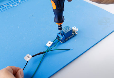
- Open the control box of the Christmas String Lights with the flat-blade screwdriver.

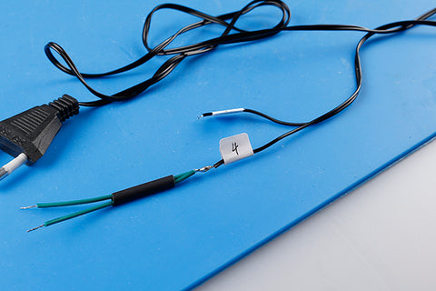
- Remove the circuit board, and stick labels on the wires and mark with (1, 2, 3, 4, 5). Note: Label number 1 covers three wires. These 3 wires are COMMON GND, LED Strip 1, and LED Strip 2. 4, 5, they are AC input ports.


- Use the electric soldering iron to remove them from the circuit board.

- Use the wire stripper to strip the electrical insulation of the wire on both sides for 1cm.

- Place three long wires on the heat-shrink tube and then connect them to the wires labeled 1, 2, and 3 with an electric soldering iron.


- After the joint portion is covered with a heat shrinkable tube, stabilizer them with the heat gun.


- Connect the two short wires to step 5 and step 6 is connected to the power plug wire labeled 4.

- Connect the wire labeled 1 and the extended wire to the power plug label 5 according to step 5 and step 6.

- Connect the wires to the labeled 2 and 3, and extend the wires to the Normal Open of the two relay modules.

- Connect the wires with 4 labels to the common end of the two relay modules.

- Connect the Raspberry Pi, T-head and breadboard. Connect the relay module to the GPIO expansion board.
-
Relay module
GPIO Extension Board
VCC
5V
GND
GND
SIG
GPIO17
SIG
GPIO18


- Hang the modified string on the Christmas tree


Secondly, let’s take care of the software
- Open Raspberry Pi after installing Raspberry Pi to RasPad
- Open Python3(IDLE)

- Create a folder

- Write the following code to the newly created folder, save it after naming the folder (suffix is .py)


#!/usr/bin/python
import RPi.GPIO as GPIO
import time
GPIO.setmode(GPIO.BCM)
# LED1 connection GPIO17
LED1 = 17
# LED2 connection GPIO18
LED2 = 18
GPIO.setup(LED1, GPIO.OUT)
GPIO.setup(LED2, GPIO.OUT)
#Pin signal is initialized to zero
def cleanup():
GPIO.output(LED1, 0)
GPIO.output(LED2, 0)
def light(status):
if status:
# LED1 light up
GPIO.output(LED1, 1)
# LED2 Put out
GPIO.output(LED2, 0)
else:
# LED1 Put out, LED2 light up
GPIO.output(LED1, 0)
GPIO.output(LED2, 1)
def light_1(led, status):
if status:
GPIO.output(led, 1)
else:
GPIO.output(led, 0)
# LED1 blink
def blink_1():
for i in range(0, 24):
light_1(LED1, 1)
time.sleep(0.307)
light_1(LED1, 0)
time.sleep(0.307)
# LED2 blink
def blink_2():
for j in range(0, 32):
light_1(LED2, 1)
time.sleep(0.307)
light_1(LED2, 0)
time.sleep(0.307)
if __name__ == "__main__":
# Pin signal is initialized to zero
cleanup()
# LED1 blink
blink_1()
# LED2 blink
blink_2()
# LED1, LED2 light up
light_1(LED1, 1)
light_1(LED2, 1)
# Hold for 0.357 seconds
time.sleep(0.357)
# LED1, LED2 light up
light_1(LED1, 0)
light_1(LED2, 0)
# LED1, LED2 alternate flashing
while True:
light(1)
time.sleep(0.307)
light(0)
time.sleep(0.307)

When the code is running, you can see lights of LED 1 interface flashes first, and then lights of LED 2 interface start to flash, the lights of LED 1 and LED 2 flash alternately every 0.307 seconds.
DONE!